
The window glass gets heavier to raise, accompanied by a sandy friction sound. The technician at the dealership may say the gear is worn. Most owners’ reaction: quality is poor. But the real cause is buried in the reduction gear’s lubrication failure — and it could have been prevented.
How Does a Window Regulator Reduction Gear Work?
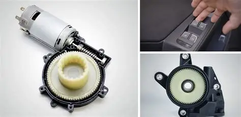
The electric window regulator’s core is a permanent magnet DC motor plus a reduction gear set. Motor speed is typically 3,000–8,000 rpm; a full window travel takes several seconds — that speed difference is entirely absorbed by the reduction gear set.
Two mainstream regulator types dominate:
- **Cable type:** Steel cable wraps around a pulley; the motor drives a spool that takes up or releases cable, moving the glass carrier along its guide rails.
- **扇形齿条 type:** The motor drives a gear, which drives a sector rack to move the glass up and down.
Regardless of structure, the reduction gear set faces several real-world challenges:
High cycle frequency. Each window travel is a complete start-stop cycle: stationary → accelerate → constant speed → decelerate → stop. Every cycle subjects the tooth root to alternating bending stress. Ten or more window operations per drive cycle is normal — the accumulated fatigue demand on gear material is substantial.
Unexpected jamming. Glass guide rails accumulating sand, door glass freezing in winter, curious children pressing the glass — all cause jam conditions. When the motor stalls, the reduction gear endures a torque spike several times the normal value, applied directly to the tooth root.
Wide temperature span. Winter door temperatures can drop to -30°C; summer sun exposure sends interior cabin temperatures above 80°C. Every start-stop cycle runs the gear through this temperature differential, placing stringent demands on grease performance stability.
────────────────────────────────────────
Two Primary Paths to Tooth Surface Wear
Tooth surface wear does not happen suddenly. It follows two typical failure paths.
Path 1: Abrasive Wear Initiating Tooth Surface Spalling
Dust and sand enter the door during use. Hard particles embed in the soft tooth surface, creating micro-cutting — repeated action produces furrows on the tooth flank, gradually degrading gear profile accuracy.
As wear worsens, effective tooth surface thickness decreases and local contact stress surges. When contact stress exceeds the tooth surface material’s load limit,大片 tooth surface material spalls from the substrate — this is tooth surface spalling.
Once spalling begins, the spalling pit edge becomes a new stress concentration point, accelerating subsequent spalling propagation. Spalling debris circulates within the gearbox, further aggravating abrasive wear — a vicious cycle.
Path 2: Fretting Fatigue Combined with Corrosive Wear
When the gear transmits torque, stress concentrates at the tooth root. Each start-stop cycle subjects the root to alternating bending stress. Grease fills the root and flank gaps, isolating metal surfaces from atmospheric moisture.
Once lubricant is lost, the root is exposed to moisture. Under combined alternating load and electrochemical corrosion, micro-cracks initiate at the root and propagate slowly along grain boundaries. Meanwhile, acid, water, and the gear surface react chemically, causing corrosive wear that accelerates surface failure.
A notable dual-edge effect exists with EP additives: EP protection versus corrosive wear. Active ingredients in EP additives form protective films in high-contact-stress zones, but if the formulation is improper, they may also aggravate corrosive wear.
────────────────────────────────────────
Lubricant Failure Is the Underlying Cause of Accelerated Wear
Reduction gear operating conditions are a textbook case of boundary lubrication and mixed lubrication alternating:
During low-speed startup the oil film is insufficient — tooth surfaces operate in boundary lubrication. During normal operation the film builds and transitions to mixed lubrication.
Ordinary greases cannot sustain reduction gears for several reasons:
Insufficient EP additive system. Greases with four-ball PB values below 294 N cannot form effective protective films when gear contact stress exceeds 500 MPa — metal-to-metal contact and wear follow immediately.
Mineral oil base stock wax precipitation at low temperatures. When ambient temperature drops below the base stock pour point, wax crystals separate from mineral oil, turning the grease semi-solid. Gears in this state can suffer visible tooth surface damage during dry cold starts lasting mere milliseconds.
Viscosity mismatch. Too high — running resistance and motor power consumption increase, with added heat generation. Too low — oil film is thin and EP capacity insufficient. Ordinary greases are not配方-optimized for reduction gear-specific operating conditions.
────────────────────────────────────────
Correct Grease Selection for Reduction Gears
Selection revolves around three core dimensions:
EP Load Capacity Is the Basic Threshold
Reduction gear tooth contact stress can reach 500–1,000 MPa. Grease PB value must reach at least 294 N; premium products require ≥600 N. The more accurate method uses ASTM D2596 Timken test to measure LWI value, directly reflecting grease load-carrying capacity under heavy gear contact conditions. Ordinary lithium-based greases typically show LWI of 200–300 N — insufficient; complex lithium soap or complex calcium sulfonate thickener systems combined with PAO base stock push LWI consistently above 400 N.
Wide-Temperature Stability Guarantees Service Life
The door operating temperature range is -40°C to +85°C. Grease cone penetration change must be controlled within reasonable limits. Industry reference: -40°C cold start torque ≤300 mN·m, ensuring no added resistance during cold starts. At high temperatures the grease must not soften or be lost, maintaining continuous lubrication capacity.
Low Noise Is the User Experience Differentiator
Gear whine frequency concentrates between 1 kHz and 8 kHz, directly correlated with the grease’s friction coefficient. Formulations with PTFE or ultra-fine MoS₂ effectively reduce tooth surface friction coefficient and suppress gear whine. Premium door motor grease requires noise ≤55 dB(A) per QC/T 590-2017.
────────────────────────────────────────
Conclusion
Solving window hesitation and noise is not complicated: pass three quality gates — select the right grease, confirm filling process, and conduct incoming inspection. When these three controls are in place, most field problems can be prevented at the selection stage.
────────────────────────────────────────
*If you are experiencing window hesitation or noise, describe the specific symptoms and I will help you determine whether it is a lubrication issue or a structural one.*