

By VNOVO Technical Support Team
A CPU converts electrical energy into computational work, with significant heat dissipating at the transistor level. High-performance CPUs generate heat flux densities that demand active thermal management. The thermal interface between the CPU die and the heat spreader is the critical path for heat removal. Any imperfection at this interface creates thermal resistance that degrades performance and longevity. Thermal paste, the primary thermal interface material at the CPU-die-to-heat-spreader interface, is selected based on thermal conductivity, pump-out resistance, and long-term stability. Getting it right at the design or assembly stage determines whether the CPU maintains its rated clock speed under sustained load without throttling.
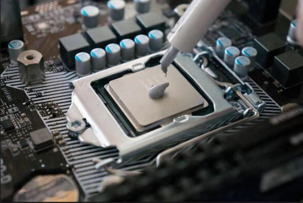
What Makes CPU Thermal Management Demanding?
– High heat flux density across an interface less than 0.1 mm thick, with no thermal mass reservoir during transient load bursts.
– Imperfect surface contact. Metal surfaces contact at microscopic high points; the thermal interface must conform to these without being squeezed out.
– Thermal cycling from full load to idle. Thermal expansion mismatch between silicon and metal pumps paste out of the contact zone.
– Sustained high temperature. At die temperatures above 85-100 degC, some base oils evaporate or oxidize, leaving a dry residue.
– Multi-material compatibility. The thermal paste must not degrade silicon, solder, copper, nickel, or die-attach materials over the service life.
– Electrical proximity near the die. In some CPU configurations the thermal interface may contact live electrical features at the die edge.
Why Do CPU Thermal Interface Problems Persist Even When Thermal Paste Is Applied?
1. Air voids from uneven application create localized dry spots that concentrate heat flow on the die.
2. Insufficient surface wetting leaves micro-gaps where metal contacts metal directly.
3. Pump-out from thermal cycling progressively reduces the effective contact area.
4. Dry-out from sustained high-temperature operation leaves a brittle residue that cannot fill surface irregularities.
5. Die-attach incompatibility causes progressive degradation of solder joints or underfill.
6. Surface coating incompatibility affects long-term thermal resistance.
What Properties Make Thermal Paste Suitable for CPU Thermal Management?
– Thermal conductivity of 2-10 W/m.K. Ceramic-filled paste, aluminum nitride or boron nitride filled, provides conductivity without electrical conductivity. Silicone-based compounds are inherently dielectric and provide a stable carrier.
– Controlled viscosity for surface wetting. Filler loading and base oil viscosity are balanced to resist pump-out under thermal cycling.
– Pump-out resistance. Fluorinated polymer bases or balanced filler loading resist migration under repeated thermal cycling.
– Long-term dry-out stability. High oxidation resistance and low vapor pressure minimize evaporation at sustained operating temperatures.
– Material compatibility with silicon, copper, nickel, and die-attach solder.
– Dielectric strength above 10 kV/mm where the thermal interface may contact live electrical features near the die edge.
How to Select the Right Thermal Paste for CPU Applications
Step 1 – Identify CPU thermal conditions:
| CPU Type | Thermal Load | Key Requirement |
| Desktop high-performance | High sustained TDP, burst load | High conductivity + pump-out resistance |
| Server / data center | Continuous high TDP, 24/7 | Oxidation stability + long-term stability |
| Embedded / industrial | Moderate TDP, wide temp range | Wide temp range + compatibility |
| Mobile / compact | Low TDP, space constrained | Low viscosity + thin-layer |
| AI accelerator / GPU-like | Very high heat flux | Maximum conductivity + pump-out tested |
Step 2 – Match formulation: Desktop: ceramic-filled paste, above 5 W/m.K, pump-out tested, metal-free. Server: oxidation-stable silicone compound, low vapor pressure. Embedded: wide-temperature silicone compound, nickel and gold compatible. Mobile: low-viscosity for thin-layer. AI accelerator: maximum conductivity ceramic-filled, pump-out validated.
Step 3 – Verify: Thermal conductivity meets budget. Pump-out resistance via thermal cycling test. Dry-out stability via high-temperature aging. Material compatibility with heat spreader finish. Dielectric strength for die-edge proximity.
Quick Reference: Thermal Paste Selection for CPU Applications
| CPU Type | Priority | Recommended Direction |
| Desktop high-performance | High conductivity + pump-out resistance | Ceramic-filled thermal paste, >5 W/m.K, metal-free |
| Server / data center | Oxidation stability + long-term stability | Silicone-based compound, low vapor pressure |
| Embedded / industrial | Wide temp + compatibility | Wide-temperature silicone compound, Ni/Au compatible |
| Mobile / compact | Thin-layer + low viscosity | Low-viscosity silicone thermal compound |
| AI accelerator / GPU-like | Maximum conductivity + pump-out tested | High-performance ceramic-filled, >8 W/m.K, pump-out tested |
How VNOVO Provides Technical Support
VNOVO does not supply off-the-shelf thermal paste with universal claims:
Application-Oriented Selection Guidance: VNOVO reviews your CPU thermal design power, heat flux density, operating temperature profile, and service life expectation, recommending thermal conductivity level, chemistry type, filler system, and viscosity grade.
Material Compatibility Verification: VNOVO helps assess candidates against your CPU heat spreader surface finish (nickel, gold, copper) and die-attach materials, confirming no corrosion, delamination, or adverse reaction.
Scenario-Based Communication Support: VNOVO explains why a direction is suggested, what trade-offs exist (high filler loading = higher conductivity but higher viscosity vs. lower filler = better wetting but lower conductivity; silicone base = excellent stability and dielectric but moderate conductivity vs. hydrocarbon base = higher conductivity but lower oxidation resistance), and what validation to prioritize.
Conclusion
When to use thermal paste for CPU thermal management
When a CPU requires a thermal interface to maintain junction temperature below the thermal design power limit, when the heat spreader-to-cooler interface requires a material to fill microscopic surface irregularities, when the CPU operates under sustained or burst thermal loads that risk throttling, or when long-term reliability depends on the thermal interface maintaining its properties throughout the product service life.
When an alternative thermal interface may be more appropriate
When the CPU uses a solder thermal interface material validated as a system, changing the die-side thermal interface is not practical. When thermal design power is low enough that passive cooling is sufficient. When the CPU module is not field-serviceable.
What VNOVO can support
1. Selection guidance: translating CPU thermal design power, heat flux density, temperature profile, and service life into thermal conductivity requirement, chemistry type, and filler specification
2. Material matching: assessing candidates against CPU heat spreader surface finishes and die-attach materials for compatibility and long-term integrity
3. Scenario communication: providing the rationale to specify, validate, and qualify the right thermal paste for your CPU thermal management design
This article is provided for informational purposes based on industry references and CPU thermal management principles. Specific thermal paste selection should always be verified through thermal resistance testing, pump-out testing, thermal cycling testing, and material compatibility confirmation for your specific CPU module and thermal design.